Getting Startd with STM32 : Pulse Width Modulation(PWM)
Published Dec. 11, 2024, 8:40 a.m. by Ezra Ogori

Introduction
In today's guide, we’ll explore how to use PWM (Pulse Width Modulation) to control the blinking of an LED on the STM32F411RE microcontroller. The focus will be on bare-metal programming—writing the code from scratch without relying on HAL or other abstraction libraries. By the end of this tutorial, you'll understand the fundamentals of PWM, the equations that define its parameters, and the steps to implement it effectively.
What is PWM?
PWM is a technique used to control the average power delivered to electronic devices by switching a digital signal on and off at a high frequency. The "on" time is known as the duty cycle, and it determines how much power is delivered.
For example, a 50% duty cycle means the signal is ON half of the time and OFF the other half. PWM is widely used for dimming LEDs, controlling motors, and other applications requiring variable power control.
PWM Equations
The frequency of the PWM signal is given by:
\[ f_{PWM} = \frac{f_{clk}}{(PSC + 1) \cdot (ARR + 1)} \]
Where:
- fclk is the input clock frequency
- PSC is the prescaler value
- ARR is the auto-reload value
The duty cycle of the PWM signal is given by:
\[ D = \frac{CCR}{ARR + 1} \times 100\% \]
Where:
- CCR is the capture/compare register value
- ARR is the auto-reload register value
Required Hardware and Software
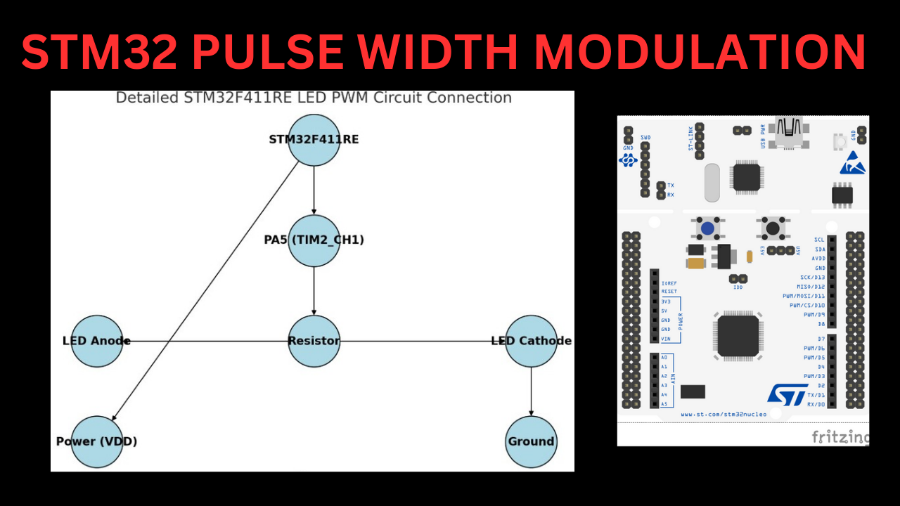
- STM32F411RE Nucleo Board.
- LED and resistor (330Ω recommended).
Hardware Connections
| Component | Pin on STM32F411RE | Description |
|---|---|---|
| LED | PA5 | Connected to TIM2_CH1 for PWM control |
| External Clock | HSE | Provides stable clock source |
| Ground | GND | Shared ground for circuit |
Step 1: Setting Up the STM32F411RE Timer for PWM
To generate a PWM signal, we will use TIM2 in PWM mode. We'll configure it to produce a 1 kHz signal with a variable duty cycle.
Step 2: Steps to Configure TIM2
- Enable the clock for TIM2 and GPIOA (for the LED pin).
- Configure GPIOA Pin 5 as Alternate Function for TIM2_CH1.
- Configure the TIM2 timer for PWM mode.
- Write to the TIM2 Compare Register to adjust the duty cycle.
- Start the timer.
Step 3: Complete Bare-Metal Code
Steps to achieve the result
Step 3.1: System Clock Setup
#include "stm32f411xe.h"

void SystemClock_Config(void) {
    RCC->CR1 |= RCC_CR_HSEON;               // Enable High-Speed External (HSE) clock
    while (!(RCC->CR1 & RCC_CR_HSERDY));    // Wait for HSE to be ready

    RCC->CFGR |= RCC_CFGR_SW_HSE;          // Select HSE as system clock
    while (!(RCC->CFGR & RCC_CFGR_SWS_HSE)); // Wait until HSE is system clock
}
Step 3.2: GPIO Setup for LED
void GPIO_Config(void) {
    RCC->AHB1ENR |= RCC_AHB1ENR_GPIOAEN;   // Enable clock for GPIOA

    GPIOA->MODER &= ~GPIO_MODER_MODE5;     // Clear mode for Pin 5
    GPIOA->MODER |= GPIO_MODER_MODE5_1;    // Set Pin 5 to Alternate Function

    GPIOA->AFR[0] |= (1 << GPIO_AFRL_AFSEL5_Pos); // Set AF1 (TIM2_CH1) for Pin 5
}
Step 3.3: Timer Setup for PWM
void TIM2_Config(void) {
    RCC->APB1ENR |= RCC_APB1ENR_TIM2EN;    // Enable clock for TIM2

    TIM2->PSC = 16 - 1;                    // Set prescaler to 16 (1 MHz timer frequency)
    TIM2->ARR = 1000 - 1;                  // Set Auto-Reload to 999 for 1 kHz PWM
    TIM2->CCMR1 |= (6 << TIM_CCMR1_OC1M_Pos); // Set PWM mode 1
    TIM2->CCMR1 |= TIM_CCMR1_OC1PE;        // Enable preload for CCR1

    TIM2->CER |= TIM_CCER_CC1E;           // Enable output on channel 1
    TIM2->CR1 = 500;                      // Start with 50% duty cycle

    TIM2->CR1 |= TIM_CR1_ARPE;             // Enable auto-reload preload
    TIM2->CR1 |= TIM_CR1_CEN;              // Enable TIM2
}
Step 3.4: Adjusting the Duty Cycle
void setDutyCycle(uint8_t dutyCycle) {
    if (dutyCycle > 100) dutyCycle = 100;  // Cap at 100%
    TIM2->CCR1 = (TIM2->ARR + 1) * dutyCycle / 100;
}
Step 3.5: Main Function
int main(void) {
    SystemClock_Config();                  // Configure system clock
    GPIO_Config();                         // Configure GPIO for LED
    TIM2_Config();                         // Configure TIM2 for PWM

    while (1) {
        for (uint8_t i = 0; i <= 100; i++) {
            setDutyCycle(i);               // Increase brightness
            for (volatile int j = 0; j < 10000; j++); // Delay
        }

        for (uint8_t i = 100; i > 0; i--) {
            setDutyCycle(i);               // Decrease brightness
            for (volatile int j = 0; j < 10000; j++); // Delay
        }
    }
}
Explanation of Code
- System Clock Setup: The microcontroller uses the HSE clock for stability.
- GPIO Configuration: Pin PA5 is set to alternate function mode for TIM2_CH1.
- Timer Configuration: TIM2 is set up for PWM mode with a 1 kHz frequency.
- Duty Cycle Adjustment: The
setDutyCycle()function modifies the brightness of the LED by changing the ON time of the PWM signal.
Conclusion
We walked through configuring PWM on the STM32F411RE in bare-metal programming. PWM offers precise control over devices, making it essential for embedded systems projects. With this foundation, you can explore more complex applications like motor control or RGB LED dimming. Keep experimenting.
Happy coding!


pHqghUme Sept. 20, 2025, 8:54 p.m.
1