Getting Started with Stm32 : RC522 RFID Reader
Published Jan. 25, 2025, 11:24 a.m. by Ezra Ogori
Introduction
In today’s guide, we’ll explore the use of RFID technology, understand its working principles, and learn how to interface the RC522 RFID module with the STM32F411RE microcontroller. We’ll also display the read RFID tag ID on an I2C LCD screen.
This project is ideal for security systems, attendance systems, and inventory management.
What We Will Cover:
 1. The RFID Technology
 2. The RC522 RFID Reader Module
 3. Introduction to I2C LCD
 4. Components Required
 6. Pin Descriptions
 7. Circuit Connection
 8. Code
1. RFID Technology
RFID (Radio Frequency Identification) is a technology that uses radio waves to identify objects or individuals. RFID systems consist of two main components:
- RFID Tag: A small device containing a unique identifier.
- RFID Reader: The device that reads the tag’s information.
The RFID reader emits electromagnetic waves to power the tag, enabling data transmission between the two.
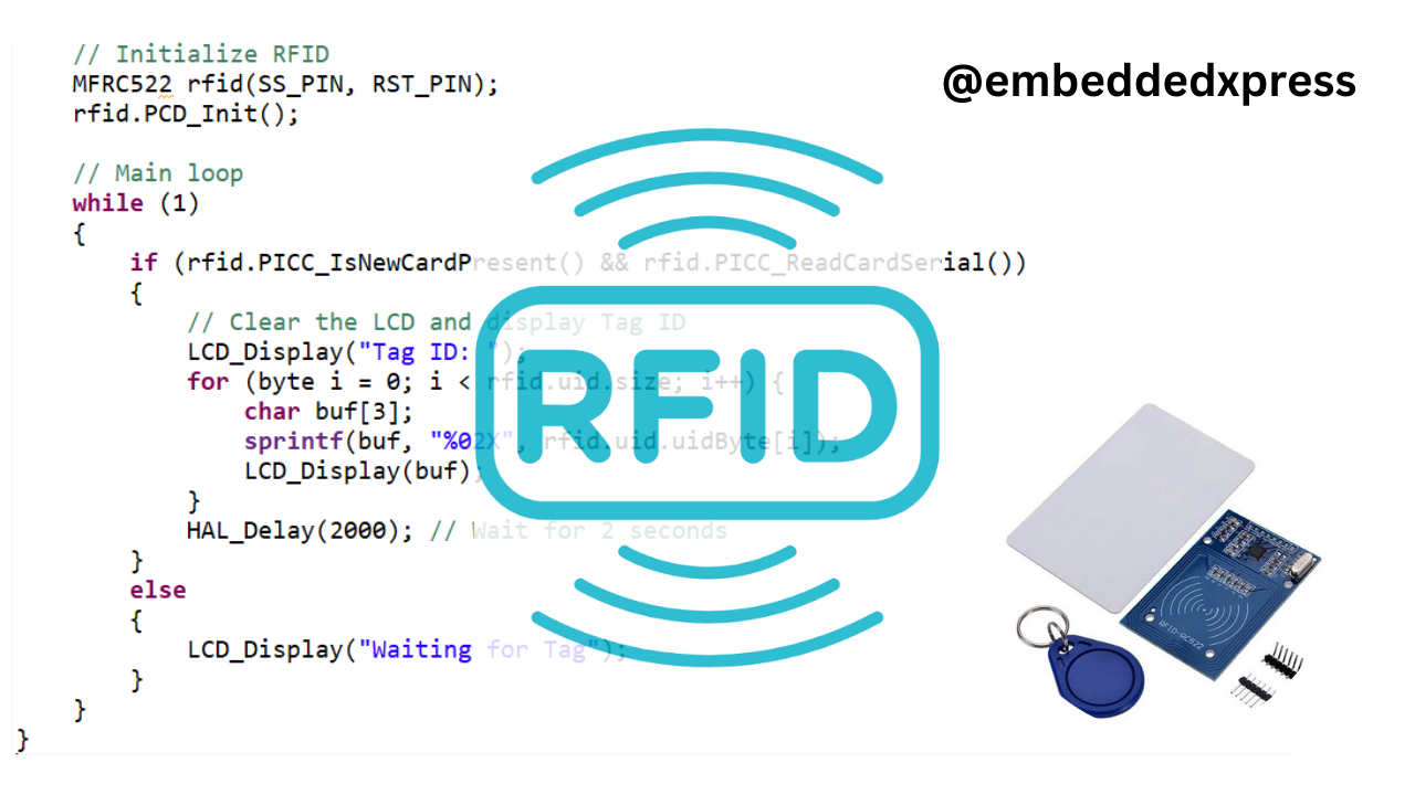
2. The RC522 RFID Reader Module
The RC522 module operates at a frequency of 13.56 MHz and is commonly used for reading RFID tags. It communicates with microcontrollers via SPI, I2C, or UART protocols.
Features of RC522:
- Operating Voltage: 2.5V–3.3V
- Max Range: 5–7 cm
- Protocols Supported: SPI, I2C, UART

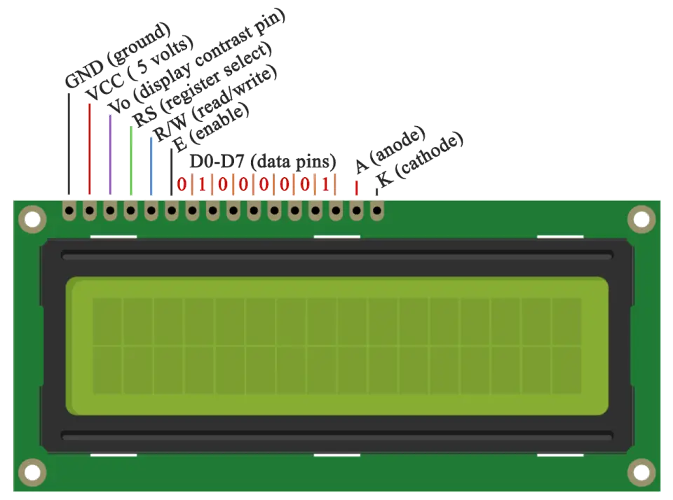
3. I2C LCD The I2C LCD is a 16x2 display module that simplifies interfacing with microcontrollers using the I2C protocol. It uses only two pins (SCL and SDA) for communication.
Features of I2C LCD:
- Backlight control
- Compact design
- Easy integration using libraries
4. Components
- STM32F411RE Nucleo Board
- RC522 RFID Module
- RFID Tags
- I2C 16x2 LCD Module
- Jumper Wires
- Breadboard
- Power Supply
Pin Descriptions
RC522 RFID Pin Description

| Pin | Description |
|---|---|
| VCC | Power Supply (3.3V) |
| GND | Ground |
| RST | Reset |
| SDA | Slave Select for SPI |
| SCK | SPI Clock |
| MOSI | SPI Master Out Slave In |
| MISO | SPI Master In Slave Out |
I2C LCD Pin Description
| Pin | Description |
|---|---|
| GND | Ground |
| VCC | Power Supply (5V or 3.3V) |
| SDA | Serial Data Line (I2C Data) |
| SCL | Serial Clock Line (I2C Clock) |
| A0, A1, A2 | Address Pins (Used to set I2C address) |
| Backlight | Controls the LCD backlight (optional) |
6. Circuit Diagram
| Component | Pin | STM32F411 Pin | Description |
|---|---|---|---|
| RFID RC522 | VCC | 3.3V | Power supply |
| RFID RC522 | GND | GND | Ground connection |
| RFID RC522 | RST | PB0 | Reset pin |
| RFID RC522 | SDA | PA4 | Slave Select (SPI SS) |
| RFID RC522 | SCK | PA5 | SPI Clock |
| RFID RC522 | MOSI | PA7 | Master Out Slave In |
| RFID RC522 | MISO | PA6 | Master In Slave Out |
| I2C LCD | GND | GND | Ground connection |
| I2C LCD | VCC | 3.3V | Power supply |
| I2C LCD | SDA | PB7 | Data line |
| I2C LCD | SCL | PB6 | Clock line |
7. Code
RC522 module:
rc522.h
#ifndef RC522_H
#define RC522_H

#include "stm32f4xx.h"

// RC522 Pin Definitions
#define RC522_RST_PIN   GPIO_PIN_0
#define RC522_RST_PORT  GPIOB
#define RC522_SS_PIN    GPIO_PIN_12
#define RC522_SS_PORT   GPIOB

// RC522 Commands
#define PCD_IDLE          0x00
#define PCD_AUTHENT       0x0E
#define PCD_RECEIVE       0x08
#define PCD_TRANSMIT      0x04
#define PCD_TRANSCEIVE    0x0C
#define PCD_RESET         0x0F

// RC522 Registers
#define CommandReg        0x01
#define CommIEnReg        0x02
#define DivIEnReg         0x03
#define FIFODataReg       0x09
#define FIFOLevelReg      0x0A
#define ControlReg        0x0C
#define BitFramingReg     0x0D
#define ModeReg           0x11
#define TxControlReg      0x14
#define TxASKReg          0x15

// Function Prototypes
void RC522_Init(void);
void RC522_Reset(void);
void RC522_WriteRegister(uint8_t reg, uint8_t value);
uint8_t RC522_ReadRegister(uint8_t reg);
uint8_t RC522_Communicate(uint8_t command, uint8_t *sendData, uint8_t sendLen, uint8_t *receiveData, uint8_t *receiveLen);
uint8_t RC522_IsNewCardPresent(void);
uint8_t RC522_ReadCardSerial(uint8_t *serial);
void RC522_SelectCard(void);

#endif
rc522.c
#include "rc522.h"

// RC522 Initialization
void RC522_Init(void) {
    // Set RST and SS as GPIO outputs
    RCC->AHB1ENR |= RCC_AHB1ENR_GPIOBEN; // Enable GPIOB clock
    GPIOB->MODER |= (0x1 << (RC522_RST_PIN * 2)) | (0x1 << (RC522_SS_PIN * 2)); // Set RST and SS as output
    GPIOB->ODR |= RC522_RST_PIN; // Set RST high
    GPIOB->ODR |= RC522_SS_PIN; // Set SS high

    RC522_Reset(); // Perform a soft reset
    RC522_WriteRegister(TxControlReg, 0x03); // Enable antennas
    RC522_WriteRegister(ModeReg, 0x3D); // Default mode settings
}

// Perform a soft reset
void RC522_Reset(void) {
    RC522_WriteRegister(CommandReg, PCD_RESET);
}

// Write to RC522 Register
void RC522_WriteRegister(uint8_t reg, uint8_t value) {
    GPIOB->ODR &= ~RC522_SS_PIN; // Select the RC522
    SPI2->DR = (reg << 1) & 0x7E; // Send address with write bit
    while (!(SPI2->SR & SPI_SR_TXE)); // Wait for transmission to complete
    SPI2->DR = value; // Send the value
    while (!(SPI2->SR & SPI_SR_TXE)); // Wait for transmission
    GPIOB->ODR |= RC522_SS_PIN; // Deselect the RC522
}

// Read from RC522 Register
uint8_t RC522_ReadRegister(uint8_t reg) {
    GPIOB->ODR &= ~RC522_SS_PIN; // Select the RC522
    SPI2->DR = ((reg << 1) & 0x7E) | 0x80; // Send address with read bit
    while (!(SPI2->SR & SPI_SR_TXE)); // Wait for transmission
    while (!(SPI2->SR & SPI_SR_RXNE)); // Wait for reception
    SPI2->DR = 0x00; // Dummy byte to receive data
    while (!(SPI2->SR & SPI_SR_RXNE)); // Wait for reception
    uint8_t value = SPI2->DR; // Read the received data
    GPIOB->ODR |= RC522_SS_PIN; // Deselect the RC522
    return value;
}

// Check if a new card is present
uint8_t RC522_IsNewCardPresent(void) {
    uint8_t result = RC522_ReadRegister(ControlReg);
    return (result & 0x01); // Return 1 if a new card is present
}

// Read card serial number
uint8_t RC522_ReadCardSerial(uint8_t *serial) {
    uint8_t status = RC522_Communicate(PCD_TRANSCEIVE, NULL, 0, serial, NULL);
    return (status == 0) ? 1 : 0; // Return 1 if successful
}
I2C LCD
lcd.h
#ifndef I2C_LCD_H
#define I2C_LCD_H

#include "stm32f4xx.h"

// LCD Address
#define LCD_I2C_ADDR 0x27

// Function Prototypes
void LCD_Init(void);
void LCD_SendCommand(uint8_t cmd);
void LCD_SendData(uint8_t data);
void LCD_Print(char *str);
void LCD_Clear(void);

#endif
lcd.c
#include "lcd.h"

// Initialize the LCD
void LCD_Init(void) {
    // Send initialization commands
    LCD_SendCommand(0x38); // Function set
    LCD_SendCommand(0x0C); // Display ON, Cursor OFF
    LCD_SendCommand(0x06); // Entry mode set
    LCD_Clear(); // Clear display
}

// Send a command to the LCD
void LCD_SendCommand(uint8_t cmd) {
    I2C1->CR1 |= I2C_CR1_START; // Generate start condition
    while (!(I2C1->SR1 & I2C_SR1_SB)); // Wait for start condition

    I2C1->DR = LCD_I2C_ADDR << 1; // Send LCD address
    while (!(I2C1->SR1 & I2C_SR1_ADDR)); // Wait for address ack
    (void)I2C1->SR2; // Clear address flag

    I2C1->DR = cmd; // Send command
    while (!(I2C1->SR1 & I2C_SR1_TXE)); // Wait for transfer complete
    I2C1->CR1 |= I2C_CR1_STOP; // Generate stop condition
}

// Send data to the LCD
void LCD_SendData(uint8_t data) {
    LCD_SendCommand(data | 0x40); // Send data with data bit
}

// Print a string on the LCD
void LCD_Print(char *str) {
    while (*str) {
        LCD_SendData(*str++);
    }
}

// Clear the LCD
void LCD_Clear(void) {
    LCD_SendCommand(0x01); // Clear display command
}
main.c
#include "rc522.h"
#include "lcd.h"

int main(void) {
    // System Clock Configuration
    SystemClock_Config();

    // Initialize GPIO, SPI, and I2C
    GPIO_Init();
    SPI_Init();
    I2C_Init();

    // Initialize RFID and LCD
    RC522_Init();
    LCD_Init();

    LCD_Print("Waiting for Tag...");

    while (1) {
        if (RC522_IsNewCardPresent()) {
            uint8_t serial[5];
            if (RC522_ReadCardSerial(serial)) {
                LCD_Clear();
                LCD_Print("Tag ID: ");
                for (int i = 0; i < 5; i++) {
                    char buf[3];
                    sprintf(buf, "%02X", serial[i]);
                    LCD_Print(buf);
                }
            }
        }
    }
}
8. Conclusion
This project demonstrates how to interface an RFID RC522 module with an STM32F411RE microcontroller to read tag IDs and display them on an I2C LCD. This setup can be extended to applications like attendance systems, access control systems, and inventory management.
Happy coding!

pHqghUme Sept. 20, 2025, 8:57 p.m.
1